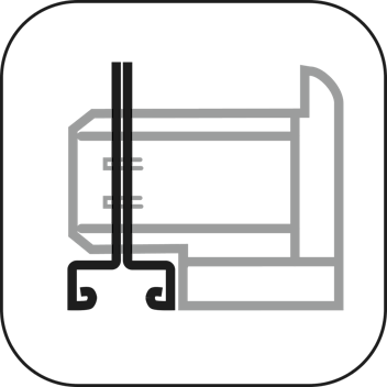
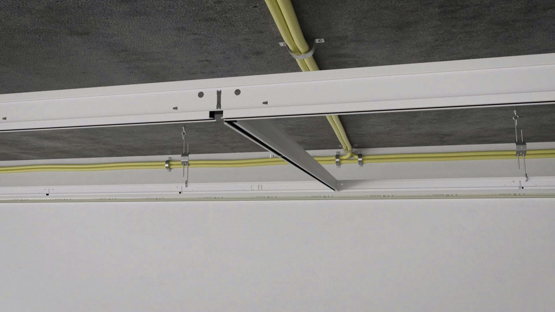
Rockfon® System Ultraline E™

Elegant ceiling expression highlighted by a narrow recess in the grid
Back
CMC_3500

Coupling

PI_BW_section_-3500_v01

Cross Section

Back

Compatible edges

Semi-concealed grid Description
E15 E15 E15-edge tiles are fitted in visible and recessed grid, which creates a shadow between the tiles. They have a straight or leaning edge and can be installed in T15 grids. The narrower T15 grid is less dominant than the wider T24 grid. Ceiling tiles with E-edges are demountable.

Compatible tiles

Tile Thickness (mm) 600 x 600 1200 x 300 1200 x 600 1500 x 300 1800 x 300
Rockfon Blanka® 20
Rockfon® Tropic 20      
Rockfon® Artic 15        

Performances

Load Bearing Load Bearing

Chicago Metallic™ Ultraline® 3500 deflection

 Kg/m²
Hanger distance (mm) Modulation (mm) Maximum deflection
2.5 mm 4.0 mm
1200 600 x 600 9.8 16.3
1200 1200 x 600 10.7 17.6
Corrosion Resistance Corrosion Resistance Class C (EN13964)
Demountability Demountability Tiles mounted in Rockfon System Ultraline E are fully demountable.
Fire Resistance Fire Resistance Some Rockfon ceiling systems have been tested and classified in accordance with European norm EN 13501-2 and/or national norms. Please contact Rockfon
Back

Chicago Metallic™ Ultraline® 3500 deflection

 Kg/m²
Hanger distance (mm) Modulation (mm) Maximum deflection
2.5 mm 4.0 mm
1200 600 x 600 9.8 16.3
1200 1200 x 600 10.7 17.6
Back
Back
Back

Perimeter Finishing Options

07

Angle trim

07

Shadow batten and angle trim

Back

Profiles and Accessories

Main runner

Component Length Height Width Product number Colours Packaging  
Main runner  
3500.tif Ultraline® main runner 3600 41 14.3 UL MR Multiple colours See Packaging Dimensions

Position of slots and suspension holes

Position of slots and suspension holes
Slots: 6 Distance between slots: 300 / 600 / 4 x 600 / 300
3500.tif Ultraline® main runner 3600 41 14.3 UL MR White 001 / White 001 (8WW) See Packaging Dimensions

Position of slots and suspension holes

Position of slots and suspension holes
Slots: 6 Distance between slots: 300 / 600 / 4 x 600 / 300

Cross tee

Component Length Height Width Product number Colours Packaging  
Cross tee  
3524.tif Ultraline® cross tee - without slots 1200 41 14.3 UL CT See Packaging Dimensions

Position of slots and suspension holes

Position of slots and suspension holes
Slots: 0 Distance between slots: / 1200 / /
3512.tif Ultraline® cross tee 600 41 14.3 UL CT Multiple colours See Packaging Dimensions

Position of slots and suspension holes

Position of slots and suspension holes
Slots: 0 Distance between slots: / 600 / /
3514.tif Ultraline® cross tee - with 1 slot 1200 41 14.3 UL CT Multiple colours See Packaging Dimensions

Position of slots and suspension holes

Position of slots and suspension holes
Slots: 1 Distance between slots: 600 / / / 600
3512.tif Ultraline® cross tee 600 41 14.3 UL CT White 001 / White 001 (8WW) See Packaging Dimensions

Position of slots and suspension holes

Position of slots and suspension holes
Slots: 0 Distance between slots: / 600 / /
3514.tif Ultraline® cross tee - with 1 slot 1200 41 14.3 UL CT White 001 / White 001 (8WW) See Packaging Dimensions

Position of slots and suspension holes

Position of slots and suspension holes
Slots: 1 Distance between slots: 600 / / / 600

Wall angle options

Component Length Height Width Product number Colours Packaging  
L Profiles  
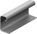
1438.tif Perimeter wall angle trim 32 x 19 x 3050mm 3050 32 19 L19x32 Multiple colours See Packaging Dimensions
W Profiles  
W_shadow_Moulding_Wall_Angle_01_00kaal_WithText.png Shadow angle 15 x 12 x 8 x 15 x 3050mm 3050 15 7.8 W8x12 Multiple colours See Packaging Dimensions

Accessories

Component Height Product number Packaging  
Ultraline®  
D7609.tif Plastic sign hanger for Ultraline® UL PSH See Packaging Dimensions
3599.tif End cap for Ultraline® slots UL CAP See Packaging Dimensions
7608.tif Bolt M6 for Ultraline® 3500 UL BOLT M6 See Packaging Dimensions
Hanger wires  
96_20.tif Hanger wire ø 2mm / L=3500mm 3500 WH 2,0 3500 See Packaging Dimensions
Back

Position of slots and suspension holes

Position of slots and suspension holes
Slots: 6 Distance between slots: 300 / 600 / 4 x 600 / 300
Back

Position of slots and suspension holes

Position of slots and suspension holes
Slots: 6 Distance between slots: 300 / 600 / 4 x 600 / 300
Back

Position of slots and suspension holes

Position of slots and suspension holes
Slots: 0 Distance between slots: / 1200 / /
Back

Position of slots and suspension holes

Position of slots and suspension holes
Slots: 0 Distance between slots: / 600 / /
Back

Position of slots and suspension holes

Position of slots and suspension holes
Slots: 1 Distance between slots: 600 / / / 600
Back

Position of slots and suspension holes

Position of slots and suspension holes
Slots: 0 Distance between slots: / 600 / /
Back

Position of slots and suspension holes

Position of slots and suspension holes
Slots: 1 Distance between slots: 600 / / / 600
Back
Back
Back
Back
Back
Back
Back

Downloads

documents


pdf
Rockfon® System Ultraline E™ | Installation Guide

pdf
DoP-RFN-UL4115MD-A02 - Ultraline® main runner

pdf
DoP-RFN-ACCVA-C03 - End cap for Ultraline® slots

pdf
DoP-RFN-ACCSUSPFIXECRD-B02 - Plastic sign hanger for Ultraline®

pdf

Videos

Video thumbnail, installation video, rockfon system Ultraline E
Video

Rockfon® System Ultraline E™

How to install Rockfon® System Ultraline E™

Video thumbnail, installation video, rockfon system Ultraline E
Video

Rockfon® System Ultraline E™

How to install Rockfon® System Ultraline E™

Back